Rotating Space V1.1
Download Rotating Space documentation in PDF format
VST plugin "Rotating Space": A 3D panner based on Head-Related Transfer Functions (HRTFs)
Rotating Space simulates a sound source (the stereo input signal) which rotates around up to ten arbitrarily definable axes.
You must use headphones to hear the effect.Consider the following arrangement:
The stereo input signal is played with two speakers. The distance between the speakers and between them and the listener
is so that the listener sees the speakers with an angle "Input Angle". This angle can be defined in the VST
plug-in via the parameter "Inp angl". If this angle is zero the speakers are at the same position.
If this angle is 180 degrees the beginning position of the speakers (before rotating) is on the y axis – the
left speaker is near to the left ear and the right speaker is near to the right ear.
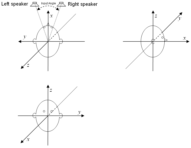
The position of the speakers in the first image is only the starting position. Over the time the virtual speakers will move around the listener while the distance to the listener keeps constant. You can determine the way in which the speakers move.
There are ten processing units (PUs) which control how the speakers will move. Apart from rotating the speakers or only one of the speakers around an axis passing the origin of coordinates, the PUs can be configured to mirror the speakers or only one of them at a plane going through the origin of coordinates and being defined by a normal vector. The rotation angle respectively the amount of mirroring can change over time. If mirroring is used, the amount of mirroring is determined by a parameter: A value of −1 means no mirroring, a value of +1 full mirroring and a value of 0 means a projection onto the mirroring plane. Changing the value from −1 to +1 results in a movement on a line between the points of no and full mirroring. However, after this (partial) mirroring transformation, the resulting vector is scaled so that its norm (length) is one again. In fact, a continuous change of the "amount of mirroring value" results in a movement of the speaker on the unit sphere.
Each PU can be used not to rotate or mirror the speakers but to do this with the axis or plane normal vector used for the rotation or mirroring beeing performed in the next PU (e.g. the rotation axis of the next PU is itself rotated around an axis defined in the actual PU).
The first PU which is configured to rotate or mirror the speakers or one of them will do this with the speakers being in the starting position which is shown in the image above. After this transformation the position of the speaker(s) will be changed further by a rotation or mirroring in the next PU which is configured to rotate or mirror the speaker(s) and so on. If there are no more PUs being configured in this way, the transformed position of the speakers is the virtual position at which the listener believes to hear the sound at the moment.
Each processing unit (PU) has the following sliders [(n) must be replaced with the number 0..9 of the processing unit]:
-
Mode(n): Controls whether the PU is off or makes of rotation (RoSpkrLR, RoSpkrL, RoSpkrR) or a mirroring (MiSpkrLR, MiSpkrL, MiSpkrR) of the speakers (..LR) or of only one of the speakers (..L or ..R). If the Mode(n) is set to "Rot NxAx" or Mir NxAx" instead, the rotation respectively mirroring will not be performed with the speakers but with the axis or normal vector which is used for the rotation or the mirroring of the next PU.
-
Speed(n), SpdMult(n): With these sliders – and possibly in combination with the global slider "Glob Spd" – the frequency with which the PU changes periodically the amount of rotation or mirroring can be determined. The position of the slider Speed(n) determines a frequency. This frequency is multiplied with the integer factor set with the slider SpdMult(n) and then – if SpdMult(n) is set between "0 * Glob" and "32*Glob" rather than between "1 factr" and "32 factr" – also with the factor set with the global slider "Glob Spd". The frequency resulting from this or these two multiplications is shown next to the slider Speed(n). It is the frequency of the periodic changes of the rotation angle or the amount of mirroring of the PU.
-
Phase(n): The phase of the periodic change of the rotation angle or the amount of mirroring of the PU.
-
wav(n): The wave form of the periodic change of the rotation angle or the amount of mirroring of the PU.
-
Min(n), Max(n): The values displayed next to these sliders are the minimal and maximal rotation angle or amount of mirroring which will be reached during the periodic change of the rotation angle or the amount of mirroring of the PU. These minimal and maximal values are not only determined by the position of the Min(n) and Max(n) sliders but also by the sliders +*MinMx(n).
-
+*MinMx(n): This slider also influences the minimal and maximal rotation angle or amount of mirroring which are displayed next to the sliders Min(n) and Max(n).
-
axis(n)x, axis(n)y, axis(n)z: These values can be set between −1 and +1 and define a direction vector used as rotation axis or plane normal vector for mirroring.
If one ore more PUs have a "speed" (frequency) which is exactly an integer multiply of the frequency of another PU than the parameter Phase(n) may be important to determine the phase of the periodic change of the rotation angles or the "amount of mirroring value".
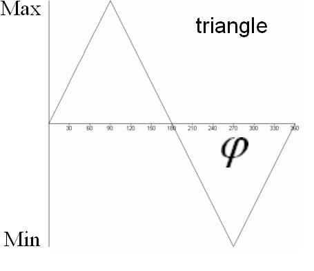
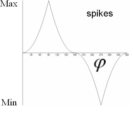
If the speed (frequency) is zero, the rotation angle or amount of mirroring is constant over time. This constant value is determined by the phase (slider Phase(n)), the waveform wav(n) and Min(n) and Max(n). Because the waveforms "sine", "triangle", "spikes", "spikes 2" or "spikes 3" (settable with slider wav(n)) have a zero value at phase zero, the rotation angle will be zero if these waveforms are selected and the phase is zero. You should set the wave form to "triangle" and the phase to 90 degrees, so that you can determine the constant rotation angle or the "amount of mirroring value" by the Max(n) slider.
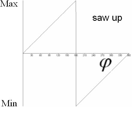
For the normal case of nonzero speed (frequency) you may want to adjust the waveform of the periodic change of the rotation angle or "amount of mirroring value". In the following diagrams the waveforms are shown which are selectable with the sliders wav(n). The abscissa is labelled with an angle φ. When starting the effect program, φ is equal to the angle which is set with the slider Phase(n). Over the time, φ will increase until it has reached 180 degrees, where it will be wrapped around to −180 degrees. From that it will increase again and so on. The frequency of this periodic change of φ is determined by the frequency which is printed next to the Speed(n) slider. The actual rotation angle or the "amount of mirroring value" is related to the actual value of φ according to the following diagrams (select the appropriate diagram on base of the waveform selected with the wav(n) slider):
If a PU is configured to rotate rather than to mirror, with the wav(n) slider you can also select "−around+" and "+around− ". The selection "−around+" is equivalent to a "saw up" waveform and "+around−" to a "saw down" waveform. In both cases the values Min(n) and Max(n) are automatically set to Min(n) = −180 degrees and Max(n) = +180 degrees, so that a continuous rotation around an axis is performed. The discontinuity of the "saw up" and "saw down" waveforms doesn't cause the rotation to be discontinuous because of the special selection of Min(n) and Max(n) (+180 degrees is equivalent to −180 degrees).
The output signal of the Rotating Space VST plugin is the sum of the following signals:
-
The dry stereo input signal after delaying by exactly 295 samples and amplifying (or attenuating) according to the "Vol Dry" slider
-
The wet (effect) stereo signal after delaying by about 295 samples (according to the position of the virtual speakers) and amplifying (or attenuating) according to the "Vol Wet" slider
Because the distance between the virtual speakers and the listener doesn't change over time, the Doppler effect doesn't play a role as would
in a Leslie speaker. To make the listener believe the speakers being in the determined positions, Rotating Space makes use of Head-Related
Transfer Functions (HRTFs).
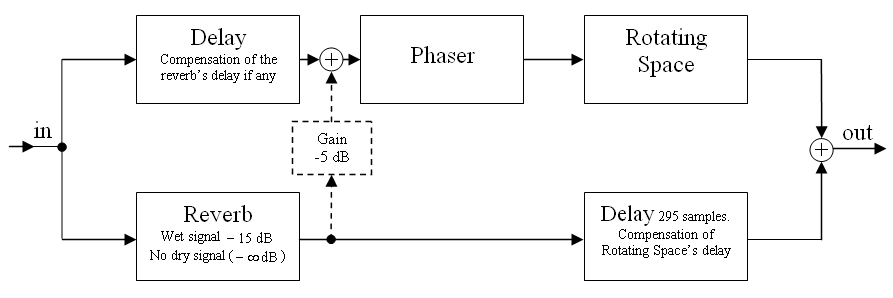
If you want to get impressive effects, take a look at the following suggestion for combining Rotating Space with a reverb and optionally a
phaser effect. Try an artificial reverb with an impulse response ending more or less abruptly after some time. This reverberation time
can e.g. be chosen to be half or a quarter of a dominant period time of the rotations in Rotating Space.
License agreement for Rotating Space:
The user is granted the right, free of charge, to use, copy, modify, alter, ameliorate and distribute this software,
subject to the following conditions:
THE SOFTWARE IS PROVIDED "AS IS", WITHOUT WARRANTY OF ANY KIND, EXPRESS OR IMPLIED, INCLUDING BUT NOT LIMITED TO THE WARRANTIES
OF MERCHANTABILITY, FITNESS FOR A PARTICULAR PURPOSE AND NONINFRINGEMENT. IN NO EVENT SHALL THE AUTHORS OR COPYRIGHT HOLDERS BE
LIABLE FOR ANY CLAIM, DAMAGES OR OTHER LIABILITY, WHETHER IN AN ACTION OF CONTRACT, TORT OR OTHERWISE, ARISING FROM, OUT OF OR IN
CONNECTION WITH THE SOFTWARE OR THE USE OR OTHER DEALINGS IN THE SOFTWARE.
Rotating Space uses the HRTFs from the slab3d project which is distributed under the
NASA Open Source Agreement.